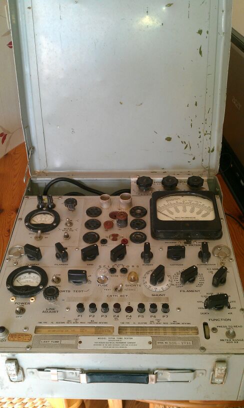

To adjust R28, connect a 220K resistorīetween pins 8 and 5 on the octal socket. The reading should be 170 volts AC plusĤ. The reading should be 36.5 volts AC plusģ. The reading should be 19 volts AC, plus or minus 1 volt.Ģ. Push switch P1 and measure pin 3 on the octal socket, the plate circuit The reading should be -3 volts plus or minus. Measure pin 5, the control grid circuit supply. The reading should be -39 volts plus or minus 1 volt.Ĥ.

Voltage should drop to 56 volts plus or minus 3 volts.ģ. Should be 130 volts plus or minus 5 volts. Push switch P4 and measure pin 4, the screen circuit supply. The reading should be 150 volts plus or minus 5 volts.Ģ. Push switch P4 and measure pin 3 on the octal socket, the plate circuit TROUBLESHOOTING section at the end of this document for assistance.ġ. Used if shunt load resistors are connected across the input to the meter.įor steps 1 and 2 use 240K. Using pin 8 on the octal socket as common, measure the following voltages Rests exactly over the LINE TEST mark in the center of the meter scale. Push switch P7 and rotate the LINE ADJUST until the meter pointer

Set the SHORTS switch to the TUBE TEST position. Set the tester programming switches to these settings: Turn on the tester and allow it to warm up for 5 minutes.Ģ. Calibration Testing of the Hickok Model 600A Tube Testerĭaniel Schoo Calibration Testing of the Hickok Model 600A Tube Tester Version 2.1, May 1997 Daniel Schooġ.


 0 kommentar(er)
